Cat 5 Wiring Diagram Wall Plate Wiring Diagram
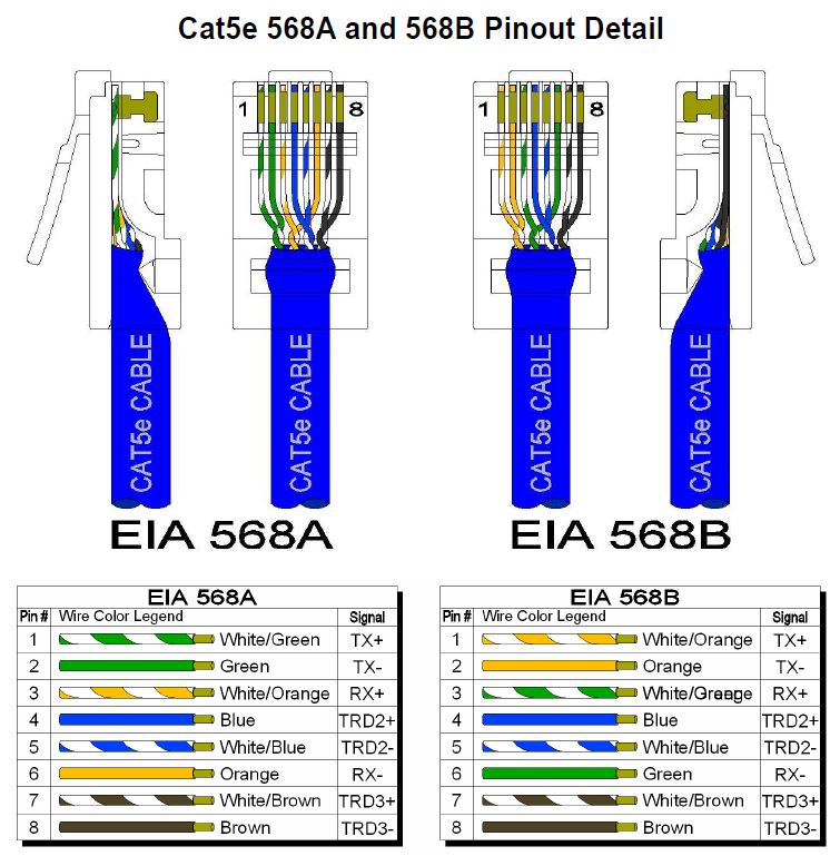
Decoding the Cat 5 Cable Diagram. The cat 5 cable diagram is like a roadmap, showing how these eight wires are arranged. There are two standards - T568A and T568B. The only difference between them is the order of the color-coded wires. Cat 5 Wiring A or B: The Colors of Connection. Cracking the color code is key to understanding the cat 5.

Cat5e Wiring A Or B
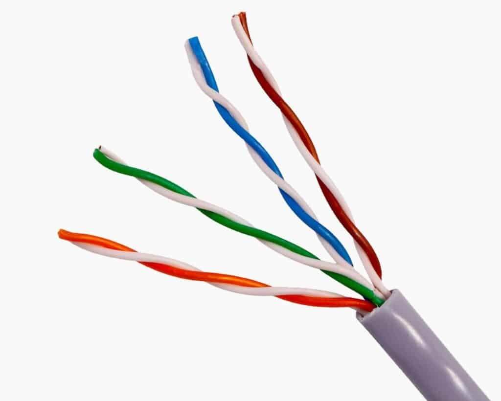
Peel off around 2 inches of the Cat5 cable's outer coating. You will see four twisted pairs, which you must untwist such that they all stand alone. You must now configure them to meet your requirements. If you desire a crossover transmission, position them using the diagram below. Picture Source: www.ertyu.org.
Stunning Cat 5 568B Photos Within Cat5 Patch Cable Wiring Diagram In
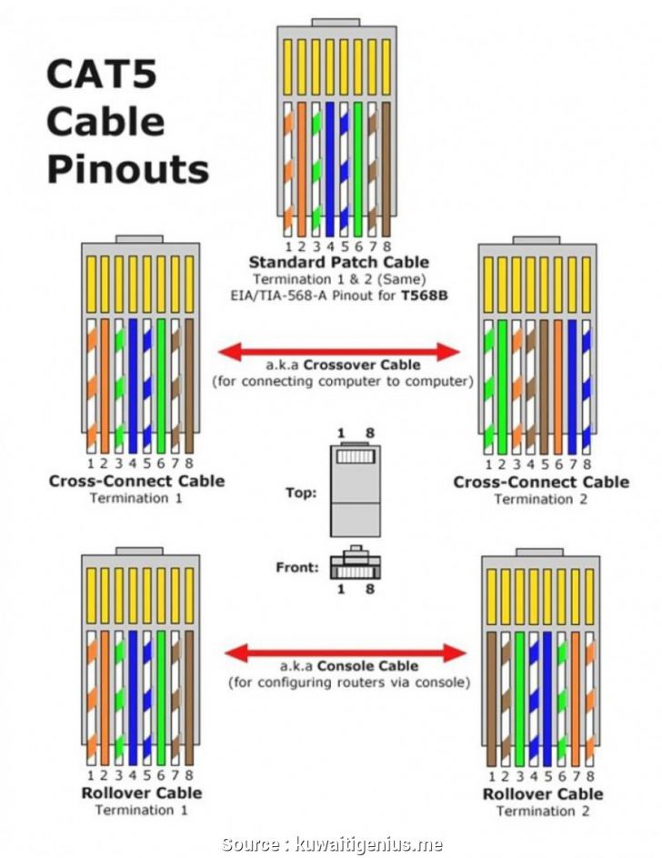
Crossover Cat5e Wiring Diagram. Crossover cables can connect a computer's Ethernet card to another without any networking equipment. Inside the cable, the wires connect the Transmit (TX) pins directly to the Receive (RX) pins and vice versa, in a cross fashion and hence the name. Most of the latest network cards are auto-sensing.
Cat5 Wiring Diagram A Complete Tutorial EdrawMax
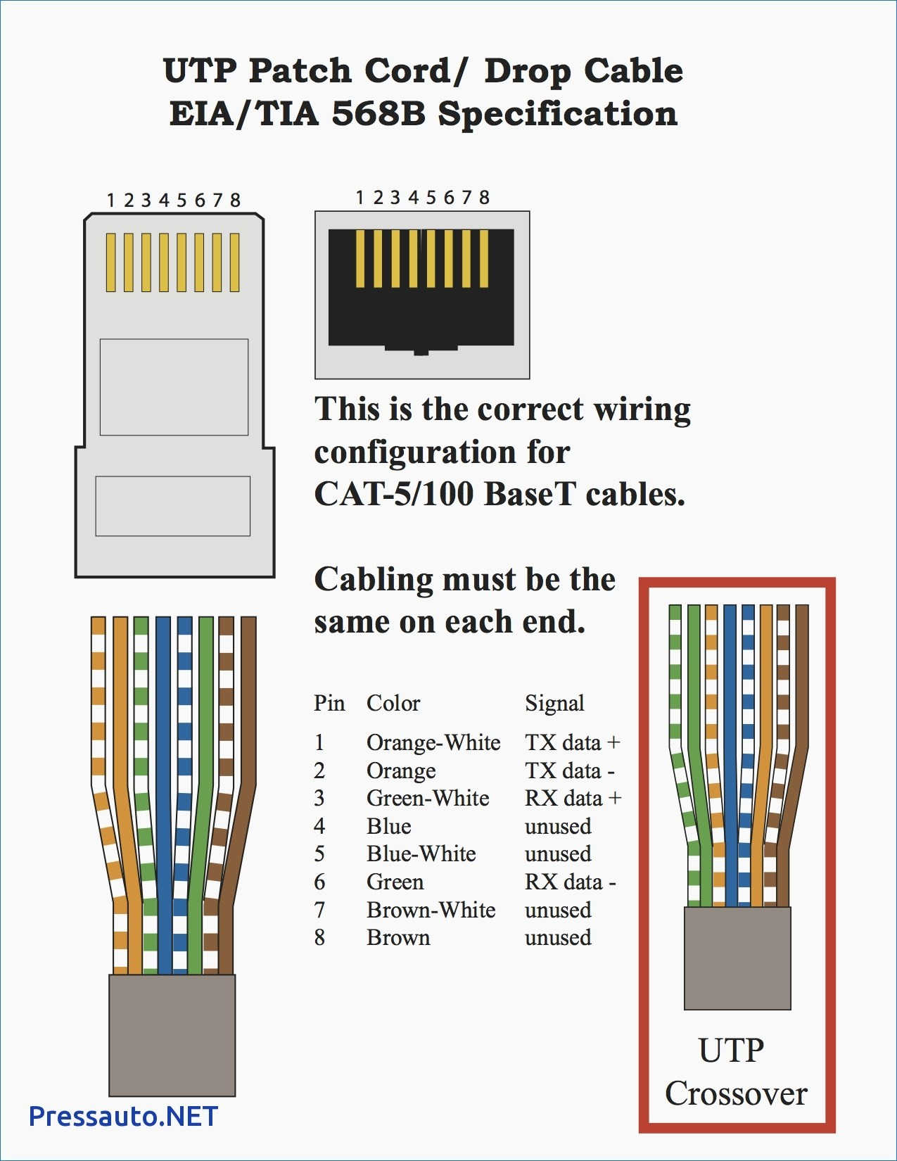
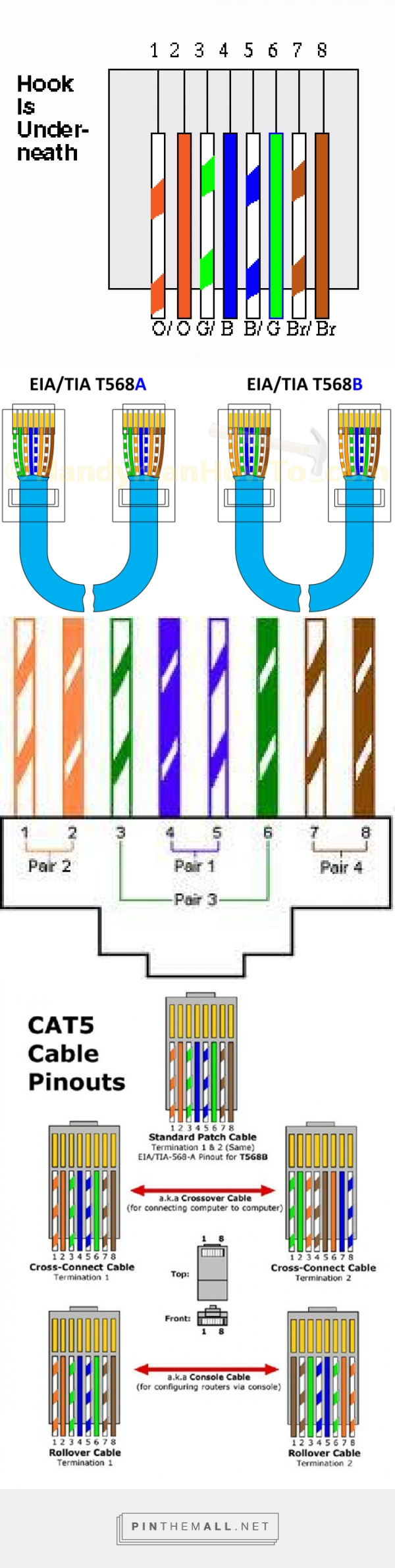
Now, we will see the crossover transmission diagram. In crossover transmission, the first end contains the orange/white and orange wires in pins 1 and 2. The wires green/white in pin 3, and in pin 4, there is a blue wire. The blue/white wires are in pin 5, and the green wire is in pin 6. Brown/white and brown wire are in the pin 7 and 8.

Cat 5 Cable Wiring
The Cat 5e cable, also known as Category 5 enhanced cable, is an upgraded version of the Cat 5 cable and is widely used for Ethernet connections. It provides a more robust and faster network performance compared to its predecessor. Understanding Cat 5e wiring diagrams is crucial for a successful installation.
Load Wiring Category 5e Wiring Diagram
This video will show you how to wire and install a RJ45 internet/network Cat 5e cable (The wall plug connector end).
Order Of Cat 5 Wires
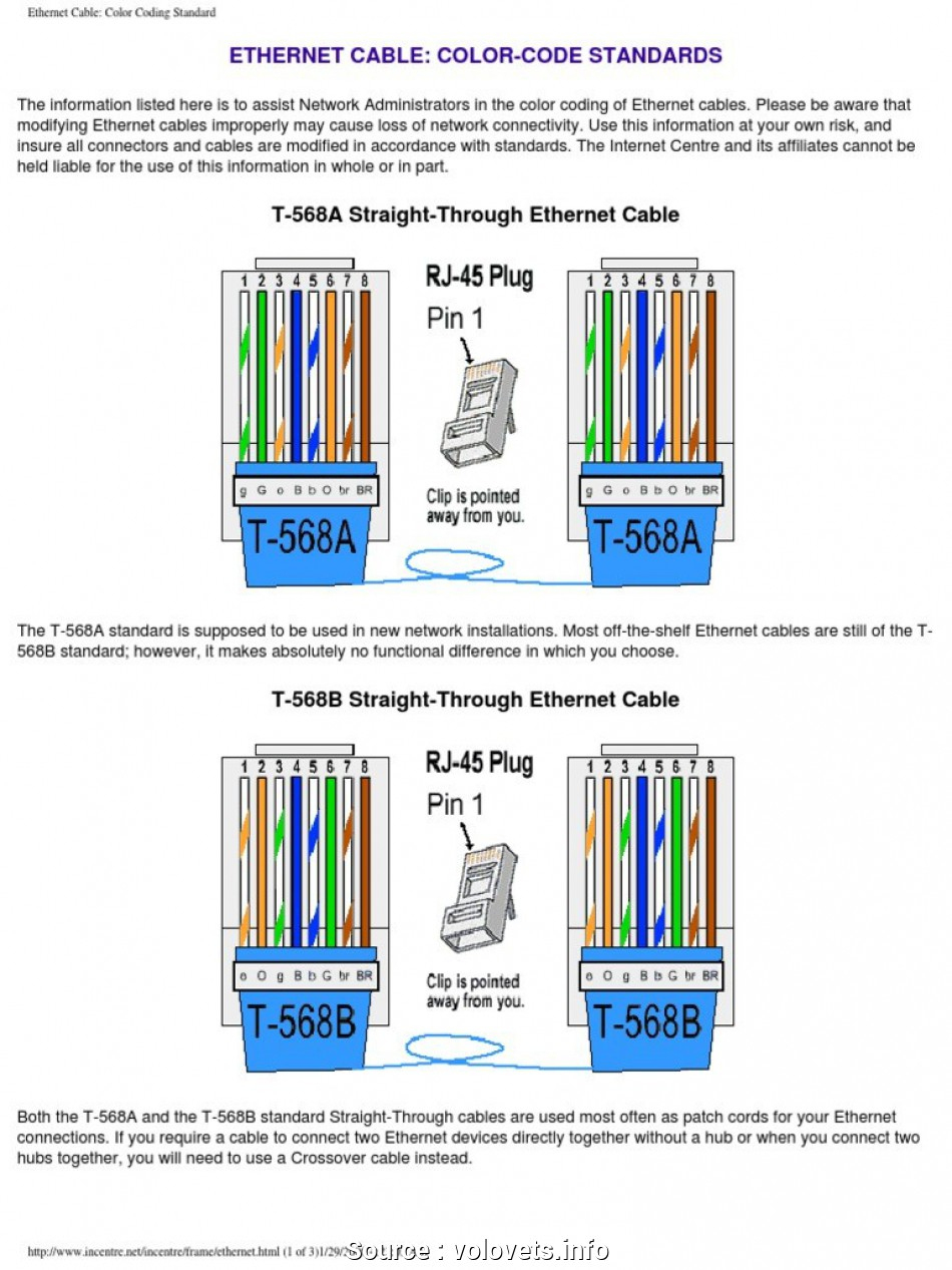
Cat5e Cable Wiring Schemes. This document provides basic background information regarding the 568A and 568B wiring standards. It will also define the differences between these standards. Instructions for creating standard and crossover cables are included in this document. The two color code schemes used to correctly wire the RJ-45 eight.

Cat 5 Cable Pin Diagram Home Wiring Software Free
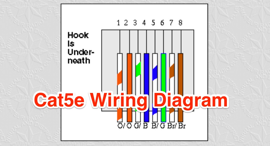
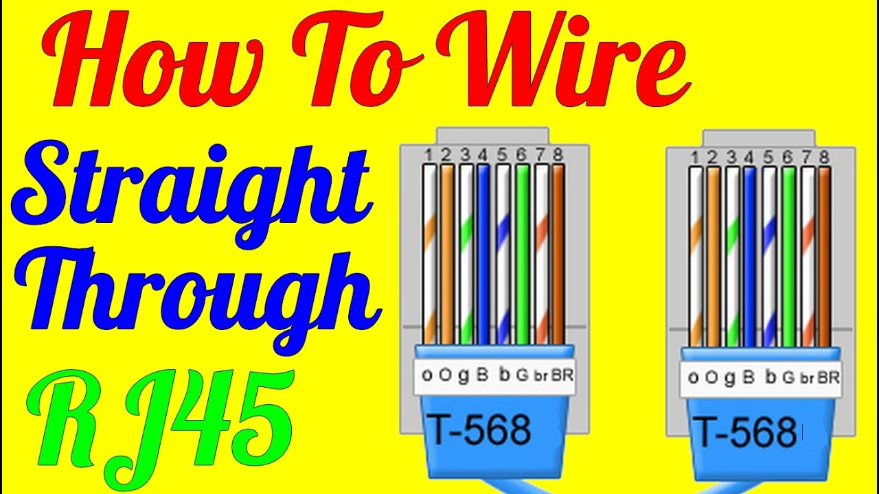
For this reason, it is important to know the steps to put one together: Using a cable stripping tool, strip about 1/3″ of the out jacket of the CAT-5 cable. Be careful not to damage any inner cables. Assemble the pairs of wires in the following order for network cables: EIA standard: TIA-568B. Insert the wires carefully into the RJ45 jack.
Cat 5 Cable Wiring Diagram
Ethernet (Cat 5) Wiring Diagrams: Category 5, Cat5, Cat5e, Cat6, Wiring Diagrams, Network Cables, Straight Through cables, crossover cables, token ring cables, RJ45, UTP, STP, wiring instructions: Straight Through (8-wire) Patch Cable: Straight Through (4-wire) Economy Patch Cable.
Cat 5 Wiring Diagram Printable Customize and Print
RESOLUTION: We use the T-568B standard for network cables. As shown in the image above, hold the RJ-45 plug with the tab facing down, and arrange the wires: orange/white - orange - green/white - blue - blue/white - green - brown/white - brown. cable cat5 cat6 diagram ethernet internet networking order wiring.

Wiring Diagram For Cat 5 Wall Jack Adapter Cable Angela Blog
First the cable modem setup. Since I moved my cable modem from my second bedroom (office) to the distribution room I needed to change the way my cable was split. Rather than the main cable into the house being split 3 ways I split things a little differently. I split the incoming cable with a 3-way splitter first.

[DIAGRAM] Cat 5 Cable Diagram
Partially stripped cable showing its four twisted pairs (eight wires). Category 5 cable (Cat 5) is a twisted pair cable for computer networks.Since 2001, the variant commonly in use is the Category 5e specification (Cat 5e).The cable standard provides performance of up to 100 MHz and is suitable for most varieties of Ethernet over twisted pair up to 2.5GBASE-T but more commonly runs at.
Cat5 Wiring Order Wiring Diagram Name Cat 5 Cable Wiring Diagram
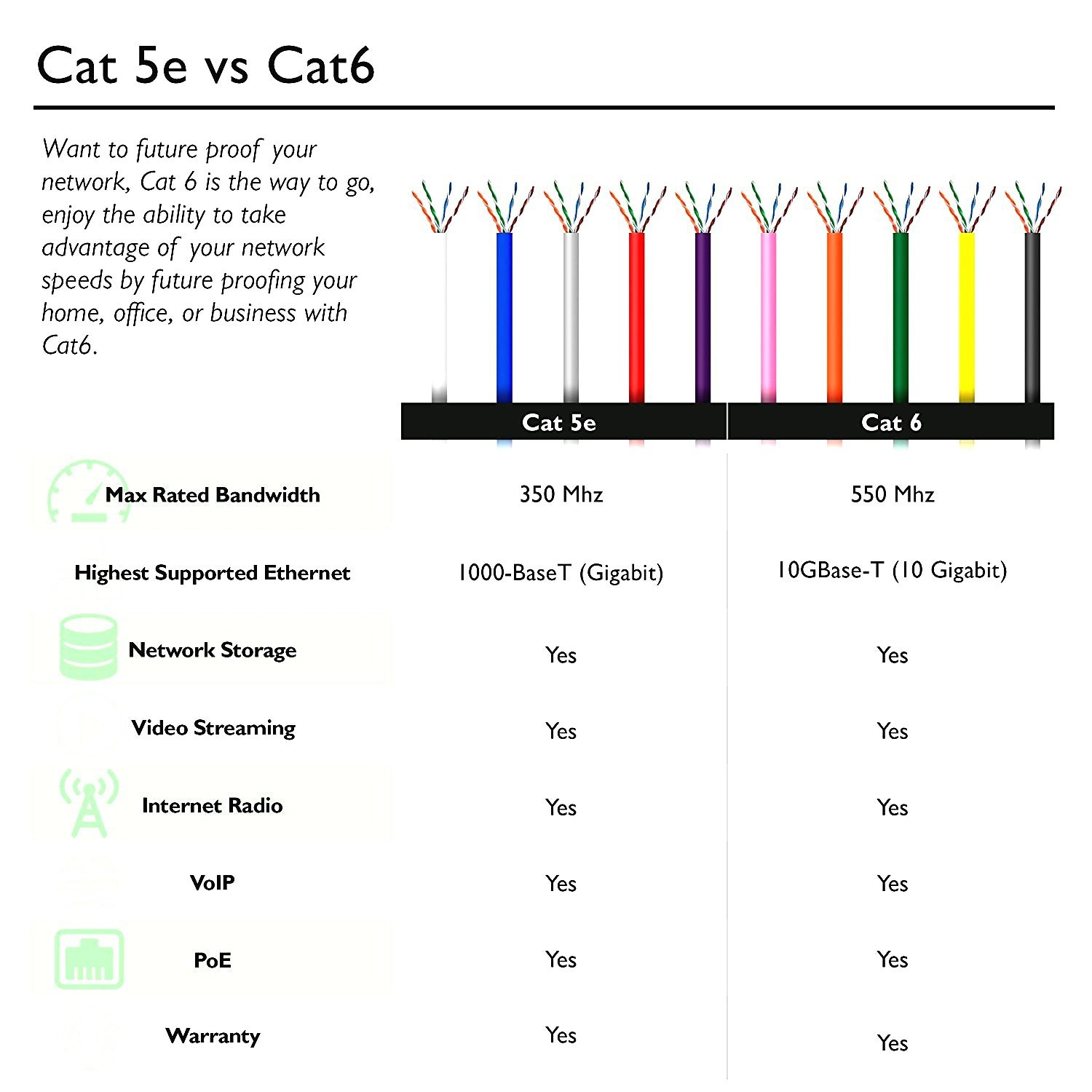
Cat 5 wiring provides a reliable and cost-effective solution for transmitting data and voice signals over short to medium distances. 2. Advantages of Cat 5 Wiring. One of the major advantages of Cat 5 wiring is its affordability. Compared to higher category cables, such as Cat 6 or Cat 7, Cat 5 cables are more economical.
Cat 5 Wiring Diagram Printable Wiring Diagram
CAT-5 Cable Installation. EIA/TIA-568B, also known as standard Ethernet, is the type of CAT-5 connection used to connect IP security cameras and network video recorders (NVRs) in IP surveillance systems.If you are creating a crossover cable, please click here for the crossover cable diagram.. Using a cable stripping tool, strip about 1/3"of the out jacket of the cat-5 cable.

Cat5e Utp Wiring Diagram
Crimp F-connectors onto the 'in' coaxial cables and screw them to the splitter terminals. Cap any unused terminals with terminating resistors. Strip the CAT-5e cables (Photos 7 and 8) and punch them into the terminals on the voice and data module, then clip off the excess wires with the electrician's scissors.
Cat 5 Wiring Diagram Pdf Cadician's Blog
3. Cut the cable to length. Determine the length needed for your cable and use the wire cutting tool on the crimping tool to cut the cable to this length. 4. Prepare the ends of the cable for crimping. Use the wire cutting tool to strip away about half an inch (12.5 mm) of the outer coating on each end of the cable.
